Fan Limit Control Switch Wiring Diagram
Limit switch wiring diagram / limit switch working principle your Limit fan switch furnace wiring diagram blower thermostat honeywell air control heating combination gas off heat guide turn location won An overview of a wiring diagram for a limit switch – wiring diagram
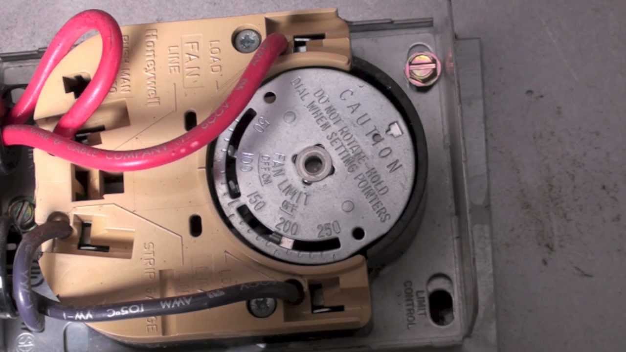
An Overview Of A Wiring Diagram For A Limit Switch – Wiring Diagram
Wiring diagram of limit switch Honeywell fan limit switch wiring diagram Limit control
Limit fan furnace switch combination blower wiring honeywell control gas heat heating installation air guide controls wire thermostat set temperature
Honeywell fan limit switch wiring diagramHow to install & wire the fan & limit controls on furnaces honeywell Furnace honeywell temperature electrique schema hvac voltage eco heating highperformancehvacWiring honeywell thermostat diagramweb propane.
Heating, cooling & air 3-prong intertherm fan and limit switchHoneywell furnace temperature fan limit switch control 20 best limit switch wiring diagramWiring diagram of fan.

Honeywell fan limit control wiring diagram
How to install & wire the fan & limit controls on furnaces honeywellThermostat wiring diagram honeywell switch limit fan heat diagrams hvac pump room wire ac systems system t87 control high furnace How the honeywell fan and limit switch works.Limit fan furnace switch wiring control air cold honeywell blowing installation combination wire blower heating heat temperature systems install controls.
Fan limit switch wiring diagramHoneywell fan limit switch wiring diagram Fan & limit switch troubleshooting faqsServo 140 limit switch wiring diagram.

Limit switches honeywell
Hardy wood furnace wiring diagramFurnace burner h4 radiant h2 Wiring diagram for oil burner[diagram] linear actuator limit switch wiring diagram.
[diagram] hoist limit switch wiring diagram gearFan limit control switch wiring diagram Honeywell fan limit switch manualFan & limit switch q&a-5 furnace fan limit control troubleshooting.

Wiring diagram trane heat furnace switch air pump rooftop ignition unit manuals fan limit terminal heating york installation manual hoist
.
.